


attila
-
Posts
6,667 -
Joined
-
Last visited
Content Type
Profiles
Forums
Events
Gallery
Posts posted by attila
-
-
Hi @FrankS
Use one oscilloscope channel to capture the filter/DUT input (Wavegen output) and the other one for the filter output, as it is used in Network or Impedance Analyzer.
Emulating the Wavegen output or sampling DAC data is not supported since these may not be precise and could be misleading. The signal can be attenuated, distorted due to current limitation, at high frequency the DAC and output latency could be significant...

-
I'm glad to hear the problem is isolated. I hope it will work after replacing the diode.
-
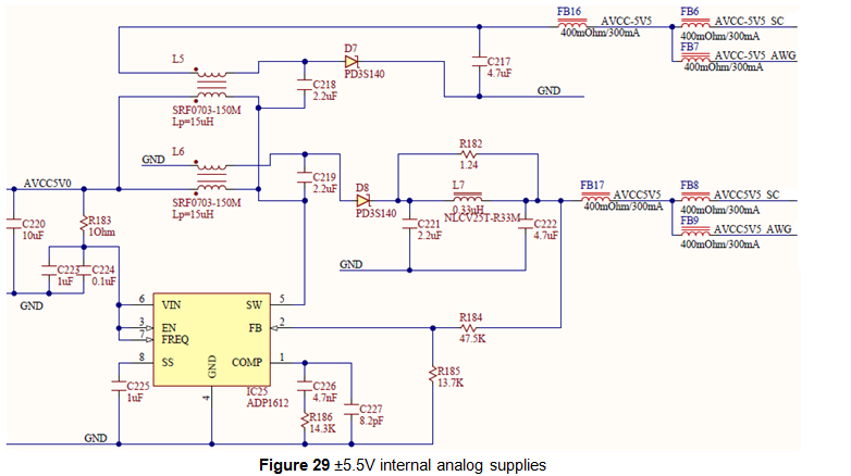
I don't know where have you measured earlier... Is the -5V5 on C217 ok? Are the ferrites good? D7? L5?
-
Hi @kaamil1984
Depending on your requirements you can use:
1. WaveForms application/ Protocol/ UART interface
2. WF app Script tool, see the following example:
3. WF SDK, see manual and examples/ py/ Digital_Uart.py

-
The +5V5 looks good but not the -5V5
See figure 30
https://digilent.com/reference/test-and-measurement/analog-discovery/reference-manual#user_voltage_supplies1
https://digilent.com/reference/_detail/analog_discovery/int7.png?id=test-and-measurement%3Aanalog-discovery%3Areference-manualHere you have top and bottom layout with marker parts/pads.


-
-
-
Hi @reddish
The embedded device (PS-AXI-PL) access requires root.
-
Hi @reddish
I run your example with Ethernet connection for 2 hour without any issues.
You could try the Linux boot mode. This is recommended for embedded use but also supports USB and Ethernet device connection. It boots slower and has a bit lower rates but the Ethernet support may be better than with the Standard boot mode (bare-metal USB and Ethernet device).The device enumeration can be filtered by connection type like: FDwfEnum(enumfilterType|enumfilterUSB, &cDev)
The connection type (DTP) of a device is only available with the following:
DWFAPI BOOL FDwfEnumEDVC(int idxDev, EDVC* pedvc);typedef DWORD DTP; const DTP dtpUSB = 0x00000001; const DTP dtpEthernet = 0x00000002; typedef DWORD PDID; // device product id typedef WORD FWVER; // device firmware version number typedef DWORD DCAP; //capabilities bitfield #pragma pack(16) typedef struct tagDVC{ char szName[cchDvcNameMax]; //in dvctable: Alias //not in dvctable: user assigned name in device //not in dvctable, no user defined name: device type with identifier char szConn[MAX_PATH+1]; //in dvctable: connection string in dvctable //not in dvctable: USB: PATHNAME // Eth: IP:192.168.1.1 // Ser: COM1:9600,N,8,1 // EPP: EPP:0x378 DTP dtp; } DVC; typedef struct tagEDVC{ DVC dvc; // standard DVC, may be used anywhere a DVC is required char szUsrName[cchUsrNameMax+1]; // user name string returned by the device char szProdName[cchProdNameMax+1]; // product name string returned by the device char szSN[cchSnMax+1];\ // serial number string returned by the device char szMAC[cchMacMax+1]; // MAC Address (EUI-48) returned by the device char szIPV4[cchIpv4Max+1]; // IPV4 address returned by the device char szIPV6[cchIpv6Max+1]; // IPV6 address returned by the device char szPort[cchPortMax+1]; // port number network device is listening on PDID pdid; // product identifier returned by the device FWVER fwver; // firmware version returned by the device DCAP dcap; // device capabilities returned by the device INT32 cOpen; // count of handles open for this device on this system union { struct { WORD discovered:1; // 0: device was not discovered during enumeration // 1: device was discovered during enumeration WORD table:1; // 0: device is not in the device table // 1: device is in the device table WORD pdidIsValid:1; // 0: pdid field is invalid // 1: pdid field is valid WORD fwverIsValid:1; // 0: fwver field is invalid // 1: fwver field is valid WORD dcapIsValid:1; // 0: dcap field is invalid // 1: dcap field is valid WORD v2FieldsValid:1; // 0: V2 fields are not valid // 1: V2 fields (ctlsSupported, dtlsSupported, // authSupported, and authEnabled) are valid WORD ctlsSupported:1; // 0: device does not support TLS on the control channel // 1: device supports TLS on the control channel WORD dtlsSupported:1; // 0: device is not in the device table // 1: device is in the device table WORD authSupported:1; // 0: client authentication is not supported // 1: client authentication is supported WORD authEnabled:1; // 0: client authentication is disabled // 1: client authentication is enabled WORD rsv:6; // reserved for future use }; WORD fs; }; } EDVC; #pragma pack()
-
Hi @tatheuss
Such you could create using the "pulse" mode, see: DigitalOut_Clock.py DigitalOut_Duty.py DigitalOut_Phase.py DigitalOut_Pins.py
or the custom examples: DigitalOut_Custom.py DigitalOut_CustomBus.py -
Hi @Someone
Officially the VIs are only supported under Windows but I've also used it under Linux and MacOS.
The vip package is basically a zip archive. This can be extracted and installed/copied manually. -
Hi @jakey
No. A WaveForms application can control one device at a time.
Multiple devices can be controlled by separate WF app instances or custom app/script.The Digital Discovery has 24 DIN and 16 DIO lines and in Logic Analyzer can use 32bits at a time.

-
Hi @HK2
Make sure the proper drivers are installed and configured.
From software all formats and sample rate up to 384kHz are supported but it depends on the underlaying libraries/drivers/hardware what is natively supported or "emulated".
The latest beta version increases the audio-output buffer which is useful at higher rate, bits and more channels:
https://forum.digilentinc.com/topic/8908-waveforms-beta-download/
-
Hi @MLopes
The automatic resistor switching is available with CV/CC and custom script but the device has minimum and maximum current limits.
In some experiments you may want to stick to a specific resistor. -
Hi @tatheuss
See the examples in the SDK/ samples/ py
Note that when the device is closed the outputs are stopped (by default), keep it open or use FDwfParamSet(DwfParamOnClose, 0) // run
-
Hi @longboard
You can ignore these.
The GUI and Qt libs are only required for the application.
The libdwf.so only requires libc6 (>=2.27) and Adept libusb-1.0-0 -
Hi @MLopes
Ideally the reference resistor should be equal to the DUT impedance otherwise the phase or magnitude measurement resolution/accuracy will be gradually reduced.
The warning is shown where the ratio between these is above 25.
It can be disabled under the Options dropdown. -
Hi @phillcau
If you are using the the BNC Adapter make sure the coupling jumpers behind the Scope sockets are in DC position and not in AC (or missing).

-
Hi @jjohnson873
It is better to use level shifter or series resistor to limit the protection current.
Connecting such voltages to AD2 DIO directly could sink significant current and your signal level could drop if the driver can't source enough. -
Hi @yohara33
The following Script should work.
You may have to adjust the thermocouple temperature conversion, the "*0.25+0.0"
if(!('Protocol' in this)) open("Protocol")
Protocol.Mode.text = "SPI"

print("Chip temperature, thermocouple temperature, eventual faults")

while(wait(1)){ // wait 1 second
    Protocol.SPI.Start()
    var bits = Protocol.SPI.Read(32, 1) // read 32 bits
    Protocol.SPI.Stop()

    var chip = ((bits<<16)>>20)*0.0625 // chip temperature, two's comp
    var temp = (bits>>18)*0.25+0.0 // thermocouple with .25*C resolution, two's comp

    var text = "Chip: "+chip+"*C\tThermo: "+temp+"*C\t"
    if(bits&0x10000 || bits&7){
        text += "Fault:"
        if(bits&4) text += " SCV"
        if(bits&2) text += " SCG"
        if(bits&1) text += " OC"
    }
    print(text)
}
-
Hi @MLopes
The next software version will have separate options for CV/CC with resistor change.

At the moment you can use the Custom with "Constant Voltage" script. See the following post:
-
-
Hi @Someone
You are right, sometimes the high sample rate can be confusing. Initially it only had 2/4/800MHz options and later added the "100MHz 32bit" option but this limits the 256MiB buffer to 64Mi Samples.
The next version will add 3rd option as you suggested.
The Record with Digital Discovery can go up to the 256MiS 800MHz 8bit just like normal (Repeated) capture.
The 1MHz note should be for the other devices, it will be removed for DD.Thank you for the observations.
-
Hi @MikeWatson
The difference I notice is that in the WF app the sampling rate is 80kHz and in you app 50kHz.
The 5V glitch may be filtered out by the lower rate average sampling.Also notice the noise band. This is a simultaneous lower rate capture of min/max samples.
It indicates that you have higher frequency components between 4.6-5.2V and glitches down to ~2.5V and up to ?7V.
Depending in the sampling rate, the 5V trigger may capture at these higher frequency components.1. Use the same sampling rate.
2. Try using the decimate filter for the trigger detector. This will look at the raw 100MHz samples rather than the default averaged samples at specified sampling rate.
FDwfAnalogInTriggerFilterSet(hdwf, filterDecimate)
Set the trigger level to at least 5.5V


"PLL not locked" error when opening waveforms
in Test and Measurement
Posted
Hi @mtoff
It could be a powering issue or damaged device.
Try using the original or other USB cables you have at hand, other USB plugs (the ones on the back of the PC), try powered USB hub, auxiliary 5V DC power supply...
See the following posts: