I am currently using the Analog Discovery 2 with the following set-up (Two first pictures).
The two resistors used here are both 10 kOhm resistors.
Using the "W1-C1-DUT-C2-R-GND" mode, I obtain the following curves third picture). As you can see, when the frequency increases, the phase becomes negative.
Using the W1-C1-R-C2-DUT-GND, I obtain the following curves (fourth picture). The set-up has been unchanged but the phase now increases with the frequency.
This can be summarized with the following picture. (fifth picture)
Is that normal? Isn't the phase curve supposed to be the same in both cases?
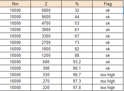
Another question I get concerns the Analog Discovery Impedance Analyzer. The datasheet says that a warning is shown when the ratio between the two resistances exceeds 25%. However, as you can see (6th picture), I only get the warning when this ratio is around 96,5%.


Question
Sinaptec
Hello,
I am currently using the Analog Discovery 2 with the following set-up (Two first pictures).
The two resistors used here are both 10 kOhm resistors.
Using the "W1-C1-DUT-C2-R-GND" mode, I obtain the following curves third picture). As you can see, when the frequency increases, the phase becomes negative.
Using the W1-C1-R-C2-DUT-GND, I obtain the following curves (fourth picture). The set-up has been unchanged but the phase now increases with the frequency.
This can be summarized with the following picture. (fifth picture)
Is that normal? Isn't the phase curve supposed to be the same in both cases?
Another question I get concerns the Analog Discovery Impedance Analyzer. The datasheet says that a warning is shown when the ratio between the two resistances exceeds 25%. However, as you can see (6th picture), I only get the warning when this ratio is around 96,5%.
Is that normal?
Best Regards
Edited by SinaptecTypo
Link to comment
Share on other sites
4 answers to this question
Recommended Posts
Create an account or sign in to comment
You need to be a member in order to leave a comment
Create an account
Sign up for a new account in our community. It's easy!
Register a new accountSign in
Already have an account? Sign in here.
Sign In Now