


davwamai
-
Posts
19 -
Joined
-
Last visited
Content Type
Profiles
Forums
Events
Gallery
Everything posted by davwamai
-
Found it. It was an inconsistency (or rather a consistency in this case) in the definitions. main() was pulling the DMA_ID for the scope rather than the awg. The projects use the same definition identifier for their respective DMA_IDs. Changing #define DMA_ID XPAR_ZMODAWG_PORTB_MM2SDMATRANSFER_0_AXI_DMA_0_DEVICE_ID -> #define DMA_ID_AWG XPAR_ZMODAWG_PORTB_MM2SDMATRANSFER_0_AXI_DMA_0_DEVICE_ID and editing the file accordingly did the trick.
- 1 reply
-
- 1
-

-
- eclypse z7
- zmod
- (and 4 more)
-
Hello, I've been struggling with an issue regarding the DDR streaming examples, more than likely of my own design, but I cannot figure out what exactly I did wrong. For context, I am currently merging the s2mm and mm2s systems into one application in order to concurrently read signals in and write signals out. The goal is to output two different signals out of each channel from the zmod dac, physically split one of the channels with a T-adapter, then use the split signal to trigger an acquisition on the zmod scope. It's running on an Eclypse Z7 with the 1410 and 1411 in ports A and B respectively. All I've done so far is merge the mm2s single transfer system project into the s2mm cyclic transfer system project. The project builds successfully. I'm encountering an error stating "Error set buf addr 128168 with 0 and FFFFFFFF, 128168." I was able to determine that xaxidma_bd.c was throwing the error, complaining that the buffer address was not correctly set. I'm not exactly sure how to interpret the difference between a 'correctly set' buffer address and an 'incorrectly set' buffer address, but I was able to reduce to something having to do with the buffer descriptor and its corresponding mask. I read that an easy solution to this was to allow unaligned transfers in the DMA in hardware, but that seems pretty irresponsible and inelegant considering the complexity of the demo. I've been apprehensive to try it since my work machine is a bit less than modest... Synthesis and Implementations take a trip to the grocery store's worth of time. I'm also interested to see where exactly I went wrong in merging the two projects, such that I can learn from that mistake and not do it again given I do merge projects again in the future. Attached are screenshots of the debugging session for reference. Thanks. edit: xaxidma.c -> xaxidma_bd.c


-
Success was a horrible choice of word to describe the wave generation aspect of the project, I may have put too much confidence in the preceeding "some." I have the DAC hooked up to an oscilloscope, and after following a few start-up guides, I found that some people went about generating their signals with a DDS compiler, so to my mind, it was the only way in existence to generate signal data. The raw signal coming out of the DAC sourcing data from the DDSC was less than desirable, an arbitrary signal that just barely resembled a sine wave. It was consistent with the required frequency, so, as per my PI's instructions, I attached a physical analog filter to the output to yield a 'cleaner' wave. I initially thought that this was an incredibly poor decision to make, since when the time came to change frequencies for another molecular sample, fiddling around in the DDSC's configuration window to find that magic combination of parameters yielded a completely different shape at our target frequency. I'd like to use this as an example to reinforce the notion that I have no idea what I am doing. After reading the first two sentences of the "Course in Communications" section of the Phasor toy README, I began questioning every design choice I have made for this project in the last few months. I've yet to have any time to play around with your design, but I'm really looking forward to learning how it works. No. I now realize that I've been far too confident in my regard to this project. I'm going to start from scratch and begin researching appropriate DMA transfer techniques, and from there worry about the platform-host transfer medium.
-
I will take a look at this. The signal we want to create is only a sine wave at 20-30MHz. We've found success with using the DDS compiler for this, but I will take a look into the phasor project out of curiosity. It looks like it would be a sound exercise for my familiarity with BRAM and HDL, and I also recently wanted to expose myself to OCTAVE.
-
This is another very important detail I have yet again failed to deliver. The stimulus signal is being generated in the PL via a DDS compiler. The DDS samples are sent directly to the low level DAC controller. Depending on the version of the controller IP, an AXIS interface is used between the DDS compiler and the controller. From what I understand the DDS compiler generates a LUT of some sort, which may be something that I would need to look into now that you mention the potential for high throughput in/out of DDR, assuming DDS samples are stored there. I'll look into this. This inconsistency is merely one way I see this project panning out. At some point storing the data for post processing as well as displaying it within a GUI in tandem will be the final implementation. Either way, the goal right now is to move the ADC data to a host machine and verify their arrival with a networking tool like wireshark. Achieving that will prompt the next step in developing systems to process and/or display the data. I was unaware of the BRAIN-1 until today. Thank you for mentioning it. It looks like a very good compromise at the expense of transfer rates.
-
You're right, I did ignore it. It was of poor etiquette to not reply after you put in the time to provide me with some pretty valuable ideas/information, and for that I apologize. Which you also suggested in the referred thread. You're correct in your assumption that I decided it was too hard. When I did begin to read into the GEM, it was admittedly overwhelming, so I mistakenly decided to give up on even attempting to understand the system entirely. The fact of the matter is that I am trying to get a comparatively complicated (to me, at least) system up and running with what very little experience and very little time I have, so I am going to default to whatever solution seems to me as the path of least resistance (in this case, it seemed like lwIP). I understand now that more effort is required to implement something as non-trivial as what I am trying to do, so I will force myself to change my mentality and not give up so easily when faced with something daunting or unfamiliar. Also true. My communicating the exact requirements of my system have been minimal, I will be sure to correct this when posting in the future. For context, this is an undergraduate research project in which I have been tasked with using the EZ7 platform to implement an analog signal acquisition/generation system for a compact NMR. The ZMod DAC will be used to generate the stimulus signal for the chemical sample, and the ZMod ADC will be used to capture the response signal from the NMR system. Both SYZYGY ports are used for each of the cards, which is also why I dismissed your suggestion of using the 1 GbE Ethernet PHY pod with a SYZYGY interface. The captured signal must be sent and stored on a host machine for post processing. The sampling rate for the ADC must be above 50Msps, which felt like an amount of data too great for a standard 12Mbaud UART channel to handle. In truth, I really do not know where to begin to determine this for sure. Instead of putting in the effort to figure out how to determine the capabilities of UART, I foolishly opted for ethernet instead. The current implementation is a doctored version of the provided Scope demo from Digilent, utilizing the zmod libraries to acquire polling into a buffer that can be used to process the contents or send them elsewhere. My plan was to take the buffer populated by the aquireImmediatePolling() function and pass it to lwip_send(), but I naively assumed that would be the end of my efforts, failing to consider opening a connection in the first place, configuing netif, etc. The PMOD headers, as you also suggested in the other thread, unfortunately do not share the same required capabilities as the zmods. With the AD5's sampling rate at 4.8kHz, it does not meet the 50Msps requirement. In the end of the previous thread you also advised me to learn the Ethernet stack, which I did immediately after reading. You wouldn't know that, because I did not reply. I began to play around with lwIP to develop my competencies and to make the top levels of the stack more familiar to me, which lead me to get too excited and start this particular thread. My knowledge is still inadequate to implement anything useful. Going forward I will figure out how the GEM works, as per your statement of that being the best solution. I do not doubt the amount of work you have put in to make the EZ7 a useful platform, for this I will trust your judgement. Again, apologies for the immaturity surrounding my interactions on this forum, as well as for my indifference towards learning what is unfamiliar. I will be sure to address these issues going forward. Thank you for the perspective.
-
Hello again. I'm in the process of developing a system based on the Eclypse Z7 board along with the 1411 and 1410 ZMods. The aim is to display the collected ADC data on a host machine oscilloscope style. Dumping the ADC buffers over UART is too slow, so I've opted for ethernet instead. The lwIP TCP server template included in SDK/Vitis makes it really easy to get high speed transfers between the PS and the host up and running quickly, which was really nice to see after struggling with other communication methods for a while. Now all that's left is getting the zmods to do cool tricks and send their results to a host machine with the help of lwIP. Small problem... the lwIP library and its template functionality is written in C, where zmodlib is written in C++. I feel like this is such a silly thing to complain about. All I really need to do is wrap the ZMOD and ZMODADC1410 C++ classes/functions in an extern and handle name mangling, but it's just a very un-fun process, especially in a fairly dense and unfamiliar library. I just wanted to put this issue out there to see if anyone had any clever ideas or suggestions on a possible workaround, to simultaneously check if anyone could find some flaw in my thinking (since I tend to get too excited and forget to take into consideration very important details) and give me time to procrastinate writing the interface code for zmodlib. Thanks, David
-
Thanks for looking into this. I'll do my best to find a workaround or another library that plays nice with 2020.1
-
I have a Vivado block design that takes ZMOD ADC data and routes the output through an AXI FIFO system and into DDR. Synthesizing the design throws multiple IP-Flow errors, starting with one that states the scope controller IP does not allow any parameter changes. [BD 41-927] Following properties on pin /ZmodScopeController_0/SysClk100 have been updated from connected ip, but BD cell '/ZmodScopeController_0' does not accept parameter changes, so they may not be synchronized with cell properties: PHASE = 0.0 Please resolve any mismatches by directly setting properties on BD cell </ZmodScopeController_0> to completely resolve these warnings. The following errors were thrown after the processing system was successfully synthesized. [IP_Flow 19-395] Problem validating against XML schema: see 'xilinx:componentInstanceExtensions' : Bad end of element [IP_Flow 19-5097] Unable to determine VLNV from IP file; verify it has the correct syntax: c:/Users/dwamai/Desktop/lwipDAQ/lwipDataAcquisition/lwipDataAcquisition.srcs/sources_1/bd/design_1/ip/design_1_ZmodScopeController_0_0/src/ZmodADC_SynchonizationFIFO.xci [IP_Flow 19-3505] IP Generation error: Failed to generate IP 'ZmodScopeController_0'. Failed to create IP subcores. [IP_Flow 19-98] Generation of the IP CORE failed. Failed to generate IP 'ZmodScopeController_0'. Failed to create IP subcores. [BD 41-1030] Generation failed for the IP Integrator block ZmodScopeController_0 I thought this might have something to do with the cloned IP library from git, since I've learned that sometimes files and folders like to magically start to malfunction. I recloned the 'vivado-library-master' repo and got the same errors. I switched to a different branch and tried 'vivado-library-artvvb-zmods' and got the same result. I followed the path thrown by IP-Flow 19-5097 to verify if the xci exists, and it does. I cross referenced the syntax with another xci file and they seemed consistent, with the vendor, library, name, and version all present. I remember that the standard clock configuration for the ScopeController required two 100MHz signals and a 400MHz signal shifted by 90 degrees. Playing around with the clock configurations with random frequencies and phases interestingly didn't throw any different errors. I am, however, working with two separate clock domains, one pulling from the PS and the other from the clock wizard's default sys_clk. I'm not sure how it works but I have a feeling this would cause timing inconsistencies that could domino-effect into errors like these. The synthesis log gave a pretty good hint, stating that the constraints file for the IP couldn't be found. I followed the path and confirmed the file was present and populated. I don't really know what to look for when it comes to a faulty xdc but I didn't see anything that stood out in the file. I'll include synth log below. *** Running vivado with args -log design_1_ZmodScopeController_0_0.vds -m64 -product Vivado -mode batch -messageDb vivado.pb -notrace -source design_1_ZmodScopeController_0_0.tcl ****** Vivado v2020.1 (64-bit) **** SW Build 2902540 on Wed May 27 19:54:49 MDT 2020 **** IP Build 2902112 on Wed May 27 22:43:36 MDT 2020 ** Copyright 1986-2020 Xilinx, Inc. All Rights Reserved. source design_1_ZmodScopeController_0_0.tcl -notrace INFO: [IP_Flow 19-234] Refreshing IP repositories WARNING: [IP_Flow 19-395] Problem validating against XML schema: see 'xilinx:packagingInfo' : Bad end of element CRITICAL WARNING: [IP_Flow 19-1977] Unable to read IP file c:/Users/dwamai/Desktop/vivado-library-artvvb-zmods/ip/Zmods/AxiStreamSinkMonitor_1.0/component.xml. This IP will not be included in the IP Catalog. WARNING: [IP_Flow 19-395] Problem validating against XML schema: see 'xilinx:packagingInfo' : Bad end of element CRITICAL WARNING: [IP_Flow 19-1977] Unable to read IP file c:/Users/dwamai/Desktop/vivado-library-artvvb-zmods/ip/Zmods/AxiStreamSourceMonitor_1.0/component.xml. This IP will not be included in the IP Catalog. WARNING: [IP_Flow 19-395] Problem validating against XML schema: see 'xilinx:packagingInfo' : Bad end of element CRITICAL WARNING: [IP_Flow 19-1977] Unable to read IP file c:/Users/dwamai/Desktop/vivado-library-artvvb-zmods/ip/Zmods/ManualTrigger_1.0/component.xml. This IP will not be included in the IP Catalog. WARNING: [IP_Flow 19-395] Problem validating against XML schema: see 'xilinx:packagingInfo' : Bad end of element CRITICAL WARNING: [IP_Flow 19-1977] Unable to read IP file c:/Users/dwamai/Desktop/vivado-library-artvvb-zmods/ip/Zmods/TriggerControl_1.0/component.xml. This IP will not be included in the IP Catalog. WARNING: [IP_Flow 19-395] Problem validating against XML schema: see 'xilinx:packagingInfo' : Bad end of element CRITICAL WARNING: [IP_Flow 19-1977] Unable to read IP file c:/Users/dwamai/Desktop/vivado-library-artvvb-zmods/ip/Zmods/UserRegisters_1.0/component.xml. This IP will not be included in the IP Catalog. WARNING: [IP_Flow 19-395] Problem validating against XML schema: see 'xilinx:packagingInfo' : Bad end of element CRITICAL WARNING: [IP_Flow 19-1977] Unable to read IP file c:/Users/dwamai/Desktop/vivado-library-artvvb-zmods/ip/Zmods/ZmodAwgAxiConfiguration_1.0/component.xml. This IP will not be included in the IP Catalog. INFO: [IP_Flow 19-1700] Loaded user IP repository 'c:/Users/dwamai/Desktop/vivado-library-artvvb-zmods'. INFO: [IP_Flow 19-2313] Loaded Vivado IP repository 'C:/Xilinx/Vivado/2020.1/data/ip'. WARNING: [Vivado 12-818] No files matched 'c:/Users/dwamai/Desktop/lwipDAQ/lwipDataAcquisition/lwipDataAcquisition.srcs/sources_1/bd/design_1/ip/design_1_ZmodScopeController_0_0/ConstrsZmodADC.xdc' ERROR: [Common 17-55] 'set_property' expects at least one object. Resolution: If [get_<value>] was used to populate the object, check to make sure this command returns at least one valid object. INFO: [Common 17-206] Exiting Vivado at Sat Jun 24 17:33:25 2023... There is probably something very obvious that I'm missing here. There isn't much information online about this particular error for this particular IP, so I figured I'd post it here for documentation's sake. Please let me know if I left out any important information regarding this issue, or is there are any other details you would like to know. Thanks.
-
Just for information's sake, I was able to get the demo working pretty much right after posting. Silly connection oversight caused a DHCP timeout, can't remember exactly what since it was a few days ago. Thanks for the reply, though.
-
I've been looking around for ways to transfer ZMOD ADC samples through ethernet (or literally any other way other than UART/SD because it is very slow for my particular application) on the Eclypse Z7 board. It seems like the only option is to use an altered version of the several lwIP examples provided in SDK/Vitis. For someone with limited experience in networking, like myself, this seems like a path of great resistance. Upon trying the demo, I quickly ran into issues such as the connection routine failing to perform a successful handshake with the board. Part of me realizes that it's time to be a big boy and learn the nuances of TCP/UDP, but I'd like to evaluate any and all possible options before I get around to it. Google presented to me what looked like my saving grace, the Tri-Mode Ethernet MAC LogiCORE IP in the form of a super neat example project done by fpgadeveloper. He was able to get the IP to do some cool tricks, like interfacing with a separate breakout board to provide the user with four different ethernet ports. The coolest part, though, was the fact that an ethernet connection (from what I can understand) is possible without the use of the PS. I got really excited at this news, as I am trying to develop a real-time analog signal acquisition and processing system, and this IP block advertising an Ethernet connection using programmable logic alone seems to be as 'real-time' as it gets. Keep in mind that I've been doing FPGA development as an undergrad student for maybe half a year, so it is more than possible that I completely misunderstood the intended applications of the IP and how it can benefit my own application. FPGAdeveloper's IP bring-up process was an Inception style example within an example, assembled for the KC705 and AC701 to interface with their on-board general purpose switches and push buttons. His walkthrough got the IP up and running (on a board I do not own), but I was still unsure as to how the thing worked. This lead me to the Product Guide, where I quickly realized I was way in over my head when I began to read the hieroglyphics that is probably incredibly useful to someone who knows what their doing. I looked around for other implementations involving similar hardware and purposes to no avail, so I decided to get my hands dirty and opened up the IP in Vivado to see if I could get an idea of how it worked. In short, I still don't get it (shocker). I started with going pin-by-pin and Googling their possible usages. It seems like the left side of the IP interfaces with an AXI EthernetLite block for data transmission, but that's really all was able to deduce. Maybe some pins should be externalized to allow DDR interfacing through EMIO, but which ones exactly are a mystery to me. I will continue to brute force an understanding of the IP by staring at the product guide until I get it. Until then, I was wondering if anyone could provide any insight on how one would use this IP to send ZMOD ADC data through ethernet to a host PC, or crush my dreams and explain to me why it's not possible. Surely it's too good to be true, but this last glimmer of hope, I feel, is still worth looking into before I resort to lwIP.
-
Hello, I am currently trying to develop a system that reads an analog signal from the ZMOD ADC and continuously sends the data over ethernet to a host machine. I figured I'd start with getting the lwIP echo server demo up and running to begin with, but I quickly ran into some problems I cannot figure out. Plainly (and because I have very limited networking knowledge to provide a more in-depth explanation), the program is stuck attempting to establish a connection to the board, printing "Trying 192.168.1.10..." then going dormant. I found what I thought could be a solution to the issue here, but unfortunately the problem persists. There is very limited information regarding the configuration of the platform BSP or the actual hardware design one should implement in Vivado to obtain a usable bitstream for this particular demo, so I went off the assumption that all that was required hardware-wise was the ZYNQ-PS after connection automation from watching a few lwIP bring-up tutorials. This is where I believe the issue is rooted. I find it hard to believe that so little is to be done to configure the GEM (or whatever is used to define the PHY functionality) sufficiently. There must be something I am missing. I'm using a platform based on a Vivado design that has other components apart from the ZYNQ PS (ADC controller, AWG controller, AXI interconnect, etc.), though none of them should interfere with the processes of the lwIP application project (I think). I've tried the low-hanging-fruit fixes, sudo telnet <ip><port>, swapping ethernet cables, connecting via ipv6, connecting via putty. I've verified that the PYNQ PS configuration for Ethernet is correct, and tried EMIO rather than MIO 52 .. 53. I'm sure that the amount of information I've provided on the issue is not enough to give anyone an idea of what the true problem is. I'm really just looking for a good place to start investigating rather than a definitive fix. I am not sure of what kind of further information I should provide, mostly because I am not sure what kind of information is useful for a circumstance like this. Please let me know if anyone has any clarifying questions and I will do my best to provide an answer to them.

-
I make up for my lack of intelligence with humor. You'd be surprised how far one can get in undergrad research with a room temp iq (and were talking Celsius). My access to a secondary machine is limited, but I'm sure I have an old laptop laying around somewhere I can put a Linux distro on. Part of me wants to put an Ubuntu VM hosted on this WIN11 PC, but I have a feeling there will be some drawbacks of doing so. I don't know exactly what said drawbacks are, so I will more than likely play it safe with a pure Ubuntu machine. I was hoping I could get away with developing this particular project with WIN11, but I trust your judgement when it comes to the relative quality of Linux as an FPGA dev environment. As for the delimiters, I was aware. Turns out that all I had to do to find the problem was get some sleep. Best
-
Hello, I am trying to get the ZMOD ADC demo working on Windows 11. I remember a post on the forum from (the man, the myth, the legend) zygot, where they mentioned it was not possible, or incredibly difficult, to get the demo working on Windows 10 due to an issue with the SYSROOT path. I am doing my best to follow the instructions of the demo very carefully, the only exception being not using the recommended operating system host. I was wondering if this particular issue has been resolved yet, since it seems like it has yet to be. I could very well be making a mistake somewhere (probably with using Windows 11), so I will list out what exactly I am doing starting from the step in the demo where we define our SYSROOT. My path is correct, since it is copy/pasted directly from the file system GUI. Checking the validity of the other two environment variables that define our working directory, PWD/CWD, I determined these were also correct. Upon applying the changes we have made to our environment variables, I notice in the outline three error symbols appear next to adcZmod, writeADCData, and adcDemo. When I hover over these definition/functions, the error thrown states "undefined reference to 'func(arbitrary param, arbitrary param, arbitrary param, ...).'" Building the project results in the following makefile throw: 16:34:49 **** Auto Build of configuration Debug for project ZmodADC1410_Demo_Linux **** make all 'Building target: ZmodADC1410_Demo_Linux.elf' 'Invoking: ARM v7 Linux g++ linker' arm-linux-gnueabihf-g++ -L"C:\Users\dwamai\Downloads\eclypse-debian-buster-armhf-sysroot_0.3/usr/lib" -L"C:\Users\dwamai\Downloads\eclypse-debian-buster-armhf-sysroot_0.3/lib" --sysroot=C:\Users\dwamai\Downloads\eclypse-debian-buster-armhf-sysroot_0.3 -o "ZmodADC1410_Demo_Linux.elf" ./src/main.o -luio c:/xilinx/sdk/2019.1/gnu/aarch32/nt/gcc-arm-linux-gnueabi/bin/../lib/gcc/arm-linux-gnueabihf/8.2.0/../../../../arm-linux-gnueabihf/bin/ld.exe: ./src/main.o: in function `writeADCData(std::__cxx11::basic_string<char, std::char_traits<char>, std::allocator<char> >, unsigned int*, unsigned char, unsigned char, unsigned int)': C:\Users\dwamai\Desktop\Eclypse-Z7-SW\ZmodADC1410_Demo_Linux\Debug/../src/main.cpp:51: undefined reference to `ZMOD::formatValue(char*, float, char const*)' c:/xilinx/sdk/2019.1/gnu/aarch32/nt/gcc-arm-linux-gnueabi/bin/../lib/gcc/arm-linux-gnueabihf/8.2.0/../../../../arm-linux-gnueabihf/bin/ld.exe: C:\Users\dwamai\Desktop\Eclypse-Z7-SW\ZmodADC1410_Demo_Linux\Debug/../src/main.cpp:55: undefined reference to `ZMOD::formatValue(char*, float, char const*)' c:/xilinx/sdk/2019.1/gnu/aarch32/nt/gcc-arm-linux-gnueabi/bin/../lib/gcc/arm-linux-gnueabihf/8.2.0/../../../../arm-linux-gnueabihf/bin/ld.exe: C:\Users\dwamai\Desktop\Eclypse-Z7-SW\ZmodADC1410_Demo_Linux\Debug/../src/main.cpp:58: undefined reference to `ZMODADC1410::signedChannelData(unsigned char, unsigned int)' c:/xilinx/sdk/2019.1/gnu/aarch32/nt/gcc-arm-linux-gnueabi/bin/../lib/gcc/arm-linux-gnueabihf/8.2.0/../../../../arm-linux-gnueabihf/bin/ld.exe: C:\Users\dwamai\Desktop\Eclypse-Z7-SW\ZmodADC1410_Demo_Linux\Debug/../src/main.cpp:59: undefined reference to `ZMODADC1410::getVoltFromSignedRaw(int, unsigned char)' c:/xilinx/sdk/2019.1/gnu/aarch32/nt/gcc-arm-linux-gnueabi/bin/../lib/gcc/arm-linux-gnueabihf/8.2.0/../../../../arm-linux-gnueabihf/bin/ld.exe: C:\Users\dwamai\Desktop\Eclypse-Z7-SW\ZmodADC1410_Demo_Linux\Debug/../src/main.cpp:60: undefined reference to `ZMOD::formatValue(char*, float, char const*)' c:/xilinx/sdk/2019.1/gnu/aarch32/nt/gcc-arm-linux-gnueabi/bin/../lib/gcc/arm-linux-gnueabihf/8.2.0/../../../../arm-linux-gnueabihf/bin/ld.exe: ./src/main.o: in function `adcDemo(unsigned char, unsigned char, unsigned int)': C:\Users\dwamai\Desktop\Eclypse-Z7-SW\ZmodADC1410_Demo_Linux\Debug/../src/main.cpp:77: undefined reference to `ZMODADC1410::setGain(unsigned char, unsigned char)' c:/xilinx/sdk/2019.1/gnu/aarch32/nt/gcc-arm-linux-gnueabi/bin/../lib/gcc/arm-linux-gnueabihf/8.2.0/../../../../arm-linux-gnueabihf/bin/ld.exe: C:\Users\dwamai\Desktop\Eclypse-Z7-SW\ZmodADC1410_Demo_Linux\Debug/../src/main.cpp:80: undefined reference to `ZMODADC1410::allocChannelsBuffer(unsigned int&)' c:/xilinx/sdk/2019.1/gnu/aarch32/nt/gcc-arm-linux-gnueabi/bin/../lib/gcc/arm-linux-gnueabihf/8.2.0/../../../../arm-linux-gnueabihf/bin/ld.exe: C:\Users\dwamai\Desktop\Eclypse-Z7-SW\ZmodADC1410_Demo_Linux\Debug/../src/main.cpp:81: undefined reference to `ZMODADC1410::acquireImmediatePolling(unsigned int*, unsigned int&)' c:/xilinx/sdk/2019.1/gnu/aarch32/nt/gcc-arm-linux-gnueabi/bin/../lib/gcc/arm-linux-gnueabihf/8.2.0/../../../../arm-linux-gnueabihf/bin/ld.exe: C:\Users\dwamai\Desktop\Eclypse-Z7-SW\ZmodADC1410_Demo_Linux\Debug/../src/main.cpp:83: undefined reference to `ZMODADC1410::freeChannelsBuffer(unsigned int*, unsigned int)' c:/xilinx/sdk/2019.1/gnu/aarch32/nt/gcc-arm-linux-gnueabi/bin/../lib/gcc/arm-linux-gnueabihf/8.2.0/../../../../arm-linux-gnueabihf/bin/ld.exe: ./src/main.o: in function `__static_initialization_and_destruction_0(int, int)': C:\Users\dwamai\Desktop\Eclypse-Z7-SW\ZmodADC1410_Demo_Linux\Debug/../src/main.cpp:29: undefined reference to `ZMODADC1410::ZMODADC1410(unsigned int, unsigned int, unsigned int, unsigned int, int, int)' c:/xilinx/sdk/2019.1/gnu/aarch32/nt/gcc-arm-linux-gnueabi/bin/../lib/gcc/arm-linux-gnueabihf/8.2.0/../../../../arm-linux-gnueabihf/bin/ld.exe: ./src/main.o: in function `ZMODADC1410::~ZMODADC1410()': c:\users\dwamai\desktop\eclypse-z7-sw\zmodlib\zmodadc1410/zmodadc1410.h:82: undefined reference to `ZMOD::~ZMOD()' c:/xilinx/sdk/2019.1/gnu/aarch32/nt/gcc-arm-linux-gnueabi/bin/../lib/gcc/arm-linux-gnueabihf/8.2.0/../../../../arm-linux-gnueabihf/bin/ld.exe: c:\users\dwamai\desktop\eclypse-z7-sw\zmodlib\zmodadc1410/zmodadc1410.h:82: undefined reference to `vtable for ZMODADC1410' collect2.exe: error: ld returned 1 exit status make: *** [makefile:50: ZmodADC1410_Demo_Linux.elf] Error 1 16:34:49 Build Finished (took 293ms) I have tried using both versions (v0.2, v0.3) of the sysroot and had the same result. I have verified that each errored function is present in their respective header declarations. I tried applying the compressed .zip as the SYSROOT as per this comment I am just trying to figure out if I have lost all sanity, or if this issue is not of my design. It would be of no surprise to me to see I have made an incredibly stupid mistake somewhere. Please let me know if anyone can figure out where I went wrong based on the information I have provided. If more is needed, I will happily share it. Best, David


-
I assumed so, I might have made a mistake while cloning the demo's repo. I'll try again to access the block design while following the demo instruction more closely this time. Thanks for the response.
-
I am trying to view the block design used to model the Zmod Scope demo that reads a signal through the ADC zmod and writes the data to a file. I would like to investigate the inner workings of the design, but cannot seem to access the block design. I noticed on the github for the demo, there are instructions detailing how one could obtain a usable Vivado project from the hardware files (now that im thinking of it, a 'Vivado Project' might not mean a pre-assembled block design). The instructions stated, In order to obtain a usable Vivado project from the demo sources, Python 3 or the Vivado TCL Console should be used: Python: python3 ./digilent-vivado-scripts/git_vivado.py checkout TCL: set argv ""; source ./digilent-vivado-scripts/digilent_vivado_checkout.tcl upon typing the tcl command into the Vivado tcl console, I do in fact get a Vivado project, but there is no block design available to see. Is there any possible way to view the block design for this particular demo, might I have done something wrong, or is it not possible to see the block design?
-
ipv6 address showing up but not ipv4 (Eclypse-Z7 Linux Demo)
davwamai posted a question in Embedded Linux
I am following the ZMOD ADC Linux demo on the Eclypse Z7 resources page(https://digilent.com/reference/programmable-logic/eclypse-z7/demos/zmod-scope). I am using Ubuntu 18.04 on my host machine and SDK 19.1 as per the instructions in the demo. I am using putty to connect to my board over ttyUSB1 in PROG and an ethernet cable between the board and my host machine. The ethernet cable labeled eth0 is showing up on both my board and my host machine when calling 'ip a' For step 6, when calling 'ip a' in putty, only the ipv6/inet6 address corresponding to eth0 shows up, and not inet/ipv4. I am required to use only ipv4 as per the instructions in the demo. I have tried modifying the /etc/network/interfaces file on my host machine and my board, using the ipv6 address in place of the ipv4 address, rebooting the host machine and board separately, removing and reestablishing eth0 with 'sudo dhclient -r eth0' and 'sudo dhclient eth0', resorting to other documented solutions to similar problems on google, and so far nothing has worked. attached are screenshots of my host machine's interfaces file, the output of 'ip a' on the board, and the output of 'ip a' on my host machine. I am not sure how to resolve this issue, any help would be greatly appreciated.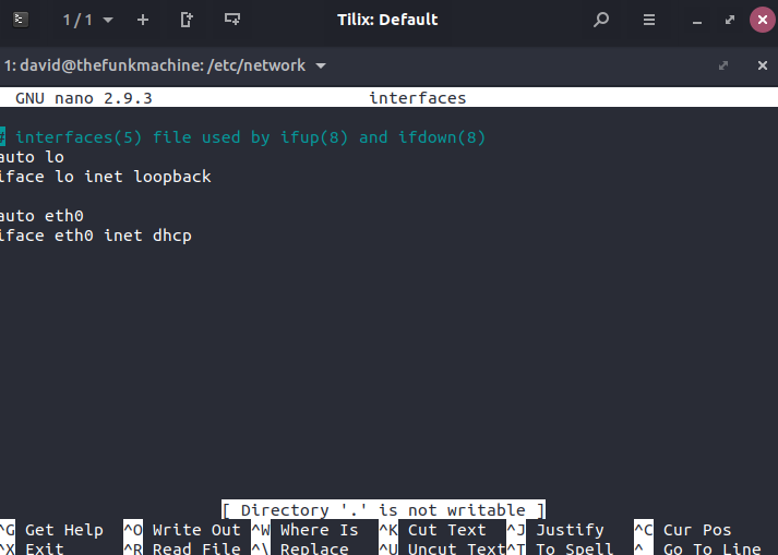


-
I am following the ZMOD ADC Linux demo on the Eclypse Z7 resources page(https://digilent.com/reference/programmable-logic/eclypse-z7/demos/zmod-scope). I am using Ubuntu 18.04 on my host machine and SDK 19.1 as per the instructions in the demo. I am using putty to connect to my board over ttyUSB1 in PROG and an ethernet cable between the board and my host machine. The ethernet cable labeled eth0 is showing up on both my board and my host machine when calling 'ip a' For step 6, when calling 'ip a' in putty, only the ipv6/inet6 address corresponding to eth0 shows up, and not inet/ipv4. I am required to use only ipv4 as per the instructions in the demo. I have tried modifying the /etc/network/interfaces file on my host machine and my board, using the ipv6 address in place of the ipv4 address, rebooting the host machine and board separately, removing and reestablishing eth0 with 'sudo dhclient -r eth0' and 'sudo dhclient eth0', resorting to other documented solutions to similar problems on google, and so far nothing has worked. attached are screenshots of my host machine's interfaces file, the output of 'ip a' on the board, and the output of 'ip a' on my host machine. I am not sure how to resolve this issue, any help would be greatly appreciated.


