


skycraper3
-
Posts
24 -
Joined
-
Last visited
Content Type
Profiles
Forums
Events
Gallery
Posts posted by skycraper3
-
-
Hello,
I'm using MCC 128 and MCC 172 for data acquisition and noticed frequency is not exact.
My application is continuous acquisition and split data at every hour reached, timestamps of these file is increasing constantly like
00:00:00.data
01:00:00.data
02:00:01.data
03:00:01.data
04:00:02.data...
, every file has exactly same size because it just appends data from "a_in_scan_read(frequency, timeout)" 3600 times to binary.This application running on 2048 Hz, and I know MCC128 has cannot achieve 2048 Hz (it shows 2047.8... Hz from a_in_scan_actual_rate()), but in MCC172 shows 2048 Hz but it drift about 0.02~0.07 seconds per hour. Of course data is continuous.
These RPis has GPS source, it syncs time from GPS every minute.
Is it normal or have to handle in code?
-
Hello, our team using MCC128 and MCC172 DAQs but suffering buzzing noise when use 3.3V MEMS microphones.
This problem occurred few months ago, but we didn't got any clues on this problem.
3.3V microphones using VCC and GND from raspberry pi 3 itself, audio output is directly connected in High channels like CH0+ or CH0H.
Microphones are tested properly and all works fine but when we starts recording on MCC128 or MCC172, we got buzzing sound during normal signals.
We tried few MEMS micrphones and also tried RaspberryPi 4 but results are not so different.
Can we get any solution or advice on this problem?
Attached images are noise plot and spectrogram, we using 4 channels, 2048 Hz sampling rates. Y axis on plot is Voltage.


-
Hello,
Is there any self-test method/callable function that board is currently working fine with all channels alive or etc. information?
Or user have to check data?Thanks, Lee
-
@heyihao This problem is currently investigating by MCC staff, also I'm still waiting response,
In short: With custom IEPE circuit, noise occurred both RPi3 and 4, but sensors work fine on NI DAQs (like USB-4432...)
-
-
I tested with 2x RPi 4B boards and 2x new power adapter, input 220V 60Hz 0.5A, output 5V 3A adapters
-
OK, I tested with Raspberry Pi 4B, that noise occurs in every minute. (New Raspi 4B and 2x new 172 HAT boards)
And I tested with my old Raspberry Pi 3B, noise was gone. (Old Raspi 3B and same boards with 4B)
Is it already known issue? Can i get some help?
-
Hello, Fausto,
- Input channels were all opened.
- Unfortunately, no spare raspberry pi atm.
- no EMF emitting devices.There is small but audible high frequency noise when DAQ(s) attached, so guessing problem in raspberry pi power supply.
Also I've tried in my home and it made AC power noise (60hz harmonic).. -
Hello, sorry for late reply,
I received new 2x MCC172 board today (nw, planned for another raspberrypi), so just tested.
Below plot from IEPE disabled and no microphones connected condition, 1 minute record at 2048hz frequency.
That noise still occurs every one minute, I'm guessing caused by raspberrypi that damaged or emitting something, is it possible?
With proper IEPE sensors, it works nicely. On 12/1/2022 at 6:56 AM, Fausto said:
Hello @skycraper3.
From your previous post, the red data represents ch1 on the master board, while the green data represents ch0 on the slave board. Is this correct? Did you try swapping cables and IEPE sensors between the channels and boards?
And yes, its correct. Tried swap cables and change boards.
-
Hello, Fausto.
I'm still investigating but ye, seems board has been damaged somehow.
-
Thanks for reply, Fausto.
Ok, I change my question,
I connected 4x PCB IEPE Microphone in 2x MCC 172, starts recording with IEPE enabled, i got this, (its OK, of course)

But when IEPE disabled with same setting, I got this one,

You can see red and green noise, that is same noise as I posted yesterday.
Is it normal? If so, what is reason of that situation?
In this question, I'm on RaspberryPi 4B (5.15.76-v7l), no other HAT boards attached.
-
Hello,
I'm using MCC 172s but having problem now, spike noise.


when 4 channels connected:
blue : master board, ch0
red : master board, ch1
green : slave board, ch0
purple : slave board, ch1 (IEPE microphone connected, others are non IEPE MICs)
These spikes occur pretty periodically, about every 1 minute when recording signal. (regardless of IEPE status)
Can I get any help about this issue? I'm using 2x MCC172 (4Ch input), some channels spike bigger and some others not.
It seems OK when connects IEPE powered microphone with preamp but when nothing connected or using non-IEPE microphone, these noise can be noticed easily.
I'm using 5V, 3A power supply. Any helps or advices would be much appreciated.
Additional question, can I use mcc172_reset() in library when making DAQ boards literally 'reset' likes when RPi board freshly turns on and nothing initialized. I just want to release GPIOs that DAQ HATs holding when initialize completed (or records)
Thanks, Lee.
-
Hello Jeffrey,
It is sad news haha 😂
Big thanks for detail reply, and clearly understood!Best regards,
Lee
-
Hello, I'm using 2 x MCC172 HAT currently, and want to use additional HAT for RS-485 serial communication.
So, purchased https://www.waveshare.com/wiki/2-CH_RS485_HAT this one that using NXP SC16IS752 chip.
My raspberry pi has now 3 HATs, RaspberryPi 4B + MCC172 + MCC172 + RS485 HAT.
At the first, I just activated NXP chip driver in /boot/config.txt and seems work.
But when starts MCC 172 data acquisition during tty capture, tty displayed garbage data (guess binary data from MCC172).I searched interface specifications of MCC 172 and found from datasheet,
QuoteRaspberry Pi™ GPIO pins used GPIO 8, 9, 10, 11 (SPI interface)
ID_SD, ID_SC (ID EEPROM) GPIO 12, 13, 26, (Board address)
GPIO 5, 6, 19, 16, 20 (clock / trigger sharing, reset, IRQ)
Data interface type SPI slave device, CE0 chip select
SPI mode 1
SPI clock rate 18 MHzSO I tried added lines on /boot/config.txt
dtoverlay=spi1-2cs,cs1_pin=17
dtoverlay=sc16is752-spi1,int_pin=24
and changed device tree overlay to CE1 chip select likes below,
/dts-v1/;
/plugin/;

/ {
	compatible = "brcm,bcm2835";

	fragment@0 {
		target = <&gpio>;
		__overlay__ {
			spi1_pins: spi1_pins {
				brcm,pins = <19 20 21>;
				brcm,function = <3>; /* alt4 */
			};

			spi1_cs_pins: spi1_cs_pins {
				brcm,pins = <17>;
				brcm,function = <1>; /* output */
			};
		};
	};

	fragment@1 {
		target = <&spi1>;
		__overlay__ {
			#address-cells = <1>;
			#size-cells = <0>;
			pinctrl-names = "default";
			pinctrl-0 = <&spi1_pins &spi1_cs_pins>;
			cs-gpios = <&gpio 17 1>;
			status = "okay";

			sc16is752: sc16is752@1 {
				compatible = "nxp,sc16is752";
				reg = <1>; /* CE1 */
				clocks = <&sc16is752_clk>;
				interrupt-parent = <&gpio>;
				interrupts = <23 2>; /* IRQ_TYPE_EDGE_FALLING */
				gpio-controller;
				#gpio-cells = <2>;
				spi-max-frequency = <4000000>;
			};
		};
	};

	fragment@2 {
		target = <&aux>;
		__overlay__ {
			status = "okay";
		};
	};

	fragment@3 {
		target-path = "/";
		__overlay__ {
			sc16is752_clk: sc16is752_spi1_0_clk {
				compatible = "fixed-clock";
				#clock-cells = <0>;
				clock-frequency = <14745600>;
			};
		};
	};

	__overrides__ {
		int_pin = <&sc16is752>,"interrupts:0";
		xtal = <&sc16is752_clk>,"clock-frequency:0";
	};
};
Unfortunately, I got error, below is dmesg results,
Quotespi-bcm2835aux fe215080.spi: cs1 >= max 1
spi_master spi1: spi_device register error /soc/spi@7e215080/sc16is752@1
spi_master spi1: Failed to create SPI device for /soc/spi@7e215080/sc16is752@1
spi-bcm2835aux fe215080.spi: cs1 >= max 1
spi_master spi1: spi_device register error /soc/spi@7e215080/spidev@1
spi_master spi1: Failed to create SPI device for /soc/spi@7e215080/spidev@1I'm not good at kernel, message seems raspberrypi-side problem, but I cannot find MCC172 overlay in boot folder.
Also hard to find reference on web, can I get any help? -
Hello, John
Thanks for helping me a lot! Works like charm, without any wire 🙂
Regards,
Lee
-
Thanks for reply, I ran modified code but no difference 😅 (added mcc172_iepe_config_write() because I'm using IEPE mic)
These are my setup,
latest Raspberry Pi OS 32bit, SPI, I2C On, using external ports - Keyboard/Mouse/HDMI
2 MCC 172 HATs, jumper installed A0 on slave HAT (upper board) - followed instruction (Installing the DAQ HAT board — MCC DAQ HAT Library 1.0.0 documentation)
IEPE sensor input with BNC splitter at master HAT (under board) CH0 and slave HAT (upper board) CH0, BNC splitter likes this
(Actually signal without splitter seems have difference so I decided to gives same input to DAQs)10-32 to BNC were connected with provided connectors and same length of each cables
-
Hello,
Tried changing clock configuring order of HATs and I even tried with C examples, but still 2~4 samples difference was detected. I'm just guessing there were only external trigger examples because these hardware issue :/
Attached file is code that i modified running option and skipping trigger routine for test.
Sincerely,
Lee
-
Hi again,
I changed codes to call start slave board first, but result is not so different just Master DAQ is faster than Slave DAQ.
Codes like:
master_hat.iepe_config_write()
slave_hat.iepe_config_write()

slave_hat.a_in_clock_config_write()
master_hat.a_in_clock_config_write()

synced = False
while not synced:
	(_, _, synced) = master_hat.a_in_clock_config_read() # for get "synced" (i also tried this for slave_hat)

slave_hat.a_in_scan_start() # with option Continuous
master_hat.a_in_scan_start() # with option Continuous

read_and_display_data_loop()

hats.a_in_scan_stop()
hats.a_in_scan_cleanup()
When I call a_in_clock_config_read() during read function, both HATs saying 'synchronized=True'... I'm confused now.
-
Hello, thanks for reply,
But I saw this sentence in MCC documentation (https://mccdaq.github.io/daqhats/index.html).
QuoteThe OPTS_EXTCLOCK option is not supported for this device and will return an error.
I'm not sure your solution works for MCC 172, could you confirm its working?
-
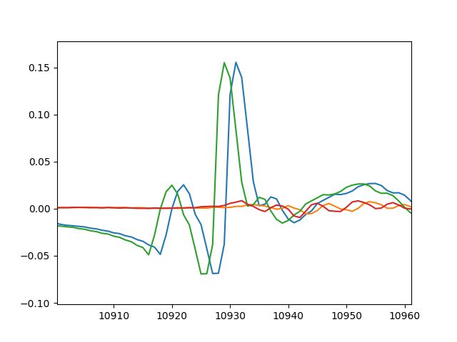
Hello,
I have 2 MCC 172 DAQs and would like to synchronous scan now, but there are only examples with external triggers. So I modified existing example like attached code, and test without external trigger. But it seem DAQs have different start time (Figure 1). I used BNC distributor so blue and green graph on Figure 1 have same input. Additionally, blue graph is data from device #0 (Master).
Is there any way to start DAQs simultaneously without external trigger or just code is wrong?
Cheers,
Lee


MCC 128 & MCC 172 frequency question
in Data Acquisition (DAQ) & Data Logging
Posted · Edited by skycraper3
Hello, @JRys.
You mean both product will eventually drift if run continuously?
If so, how can I handle it or any tips?