


PhilipW
-
Posts
25 -
Joined
-
Last visited
Content Type
Profiles
Forums
Events
Gallery
Everything posted by PhilipW
-
Do you data loggers support linear position sensors? These sensors are sometimes referred to as linear encoders. Omega has a sensor for linear position with their data loggers. The sensor uses analog output. Cheers
-
In an earlier post, you suggested I use DConfigPort() or DConfigBit(). If I use DConfigBit(AuxPort, 0, DigitalOut) I have to wire screw terminal DIO0 since bitNum=0. If I use DConfigPort(AuxPort, DigitalOut) which bitNum is being used? Which screw terminal do I wire?
-
So the I/O port has four-bits (0 - 3) Do these bits correspond the screw terminals labelled DIO0, DIO1, DIO2 and DIO3?
-
To clarify, a digital port (AUXPORT) consists for 4 digital I/O lines. For the USB-1808X there are 4 screw terminals labelled DIO0, DIO1, DIO2 and DIO3. By default each I/O line has four bits. The maximum value for the digital port is 16 bits = 2^16 - 1 = 65,535 ? Can I configure the number of I/O lines are in digital port ? Can I configure the number of bits in an I/O line ? Could I configure AUXPORT to only use DIO0 and DIO0 have 16 bits?
-
thank you
-
Using 3 analog inputs and 1 counter I am able to receive voltage and encoder data simultaneously using DaqInScan() on a USB-1808X. The scan options include MacDaq.ScanOptions.Background and MccDaq.ScanOptions.Continuous. Now I want to include occasional digital output. Within an application a user will click a button and the following code will be executed: ushort DataValue = 255; PortOutputNum = MccDaq.DigitalPortType.AuxPort; MccDaq.ErrorInfo ULStat = daqBoard.DOut(PortOutputNum, DataValue); The universal library returns the error: Digital port not configured correctly for requested operation. What I’m I doing wrong?
-
I’m using the USB-1808X. On the device there are labels for DIO0, DIO1 and GND. I assume that the label refer to digital input 0, digital input 1 and ground. Within the code short[] channelArray = null; MccDaq.ChannelType[] channelTypeArray = null; int numberOfDigitalChannels = 1; channelArray = new short[numberOfDigitalChannels]; channelTypeArray = new MccDaq.ChannelType[numberOfDigitalChannels]; channelTypeArray[0] = MccDaq.ChannelType.Digital; channelArray[0] = 0; // port 0 When I call daqBoard.DaqInScan(), I get the exception message “Invalid digital port number” Is there no port 0? If I use channelArray[0] = (short)MccDaq.DigitalPortType.AuxPort; // port 1 calling daqBoard.DaqInScan() is successful. I noticed that for enumerated type DigitalPortType, there is no enumeration whose value is 0. How do I access digital Input 0? public enum DigitalPortType { AuxPort = 1, AuxPort0 = 1, AuxPort1 = 2, AuxPort2 = 3, FirstPortA = 10, FirstPortB = 11, FirstPortC = 12, FirstPortCL = 12, FirstPortCH = 13, SecondPortA = 14, SecondPortB = 15, SecondPortCL = 16, SecondPortCH = 17, ThirdPortA = 18, ThirdPortB = 19, ThirdPortCL = 20, ThirdPortCH = 21, FourthPortA = 22, FourthPortB = 23, FourthPortCL = 24, FourthPortCH = 25, FifthPortA = 26, FifthPortB = 27, FifthPortCL = 28, FifthPortCH = 29, SixthPortA = 30, SixthPortB = 31, SixthPortCL = 32, SixthPortCH = 33, SeventhPortA = 34, SeventhPortB = 35, SeventhPortCL = 36, SeventhPortCH = 37, EighthPortA = 38, EighthPortB = 39, EighthPortCL = 40, EighthPortCH = 41 }
-
Find rotation using quadrature encoder in USB-1808X
PhilipW replied to PhilipW's question in Measurement Computing (MCC)
Hi Fausto, And to configure the quadrature encoder, I must use the following parameters? MccDaq.CounterMode Mode = MccDaq.CounterMode.Encoder | MccDaq.CounterMode.EncoderModeX1; MccDaq.CounterDebounceTime DebounceTime = MccDaq.CounterDebounceTime.DebounceNone; MccDaq.CounterDebounceMode DebounceMode = 0; MccDaq.CounterEdgeDetection EdgeDetection = MccDaq.CounterEdgeDetection.RisingEdge; MccDaq.CounterTickSize TickSize = 0; int MapCounter = 0; int counterChannel = 2; // encoder channels are 2 and 3 daqBoard.CConfigScan(counterChannel, Mode, DebounceTime, DebounceMode, EdgeDetection, TickSize, MapCounter); -
Find rotation using quadrature encoder in USB-1808X
PhilipW posted a question in Measurement Computing (MCC)

-
Screw terminals for quadrature encoder in USB-1808X
PhilipW posted a question in Measurement Computing (MCC)
The USB-1808X has 2 general purpose counters (0 and 1). There are also 2 counters for the quadrature encoder (2 and 3). In the wiring assignment, does counter 2 (quadrature encoder) correspond to screw terminals ENC0A, ENC0B and ENC0Z? Does counter 3 (quadrature encoder) correspond to screw terminals ENC1A, ENC1B and ENC1Z? Regards, Philip -
Hi Fausto, Did you have any thoughts on my example code?
-
Hello Fausto, Sorry I could not respond earlier. I had other commitments. I've provided a sample application. I connected it to a USB-1808X. A Turck encoder is attached to the USB-1808X. The application can use the digital input or a counter. The application generates a text file which shows information. Data is collected and processed each second. The samples per channel per second is 2500. Data is collected with DaqInScan(). If using digital input, the application counts the rising edges ("0" followed by "1") to determine the number of pulses per second. I'm trying to show that using digital input or a counter will produce the same number of pulses per second. See attached zip file. Regards, Philip WpfAppEncoderPulses.zip
-
If I use digital input (MccDaq.ChannelType.Digital16) I am able to read the output from an Turck encoder. The output looks like the following: 0 0 0 1 1 0 1 1 0 0 0 0 1 1 1 0 0 0 0 0 0 0 1 1 1 0 0 1 0 0 0 0 1 1 1 0 0 1 0 0 0 0 1 1 1 0 0 0 1 1 0 1 1 1 1 0 0 0 1 1 0 0 1 0 0 0 0 1 1 1 0 0 1 0 0 0 0 1 1 1 0 0 ... The output is a square wave. The samples per channel per second is 2500. I wrote a method to count the pulses per second and the average pulse count is around 900. If I use a counter (MccDaq.ChannelType.Ctr) to process the output from the Turck encoder and configure the counter as follows: MccDaq.CounterMode Mode = MccDaq.CounterMode.Totalize; MccDaq.CounterDebounceTime DebounceTime = MccDaq.CounterDebounceTime.DebounceNone; MccDaq.CounterDebounceMode DebounceMode = 0; MccDaq.CounterEdgeDetection EdgeDetection = MccDaq.CounterEdgeDetection.RisingEdge; MccDaq.CounterTickSize TickSize = 0; int MapCounter = 0; uLStat = daqBoard.CConfigScan(CounterNum, Mode, DebounceTime, DebounceMode, EdgeDetection, TickSize, MapCounter); The output looks like the following: 0 1 1 1 3 4 5 5 5 6 7 8 8 8 10 11 12 12 12 12 14 15 15 15 16 17 18 19 19 20 21 22 22 22 23 24 25 26 26 26 28 29 29 29 30 31 32 32 32 34 35 36 36 36 36 38 39 ... The samples per channel per second is also 2550. The average pulse count per second is around 3500. Any idea why my pulse counts don't match? In the encoder data, when a 1 follows a 0, is it a rising edge? Regards, Philip
-
USB-1808X using a counter to count pulses from an encoder
PhilipW replied to PhilipW's question in Measurement Computing (MCC)
The online help for CConfigScan() and the only example program for counter type Counters.clsCounters.CTRQUAD (ClnScan03) indicate that the input channel counts pulses. In your last post, you indicate that the input channel measures distance. You mention a resolution of 1200. What is the 1200? Does your software need to know the length of the conveyor belt? You mentioned a length of 10 feet in your last post. How would you configure CConfigScan() with the values in your last post? -
USB-1808X using a counter to count pulses from an encoder
PhilipW replied to PhilipW's question in Measurement Computing (MCC)
You are correct to say that it would be nice if there was a status register that indicated direction. I have a situation where a conveyor belt has ONE speed (pulses per second = 392) and can go forward (clockwise) or backwards (counter clockwise). 1. From a stopped position (pulses per second = 0), the conveyor belt moves forward and the pulses per second is 392 2. From a stopped position (pulses per second = 0), the conveyor belt moves backward. Will the pulses per second be -392 since the USB-1808X decrements the pulse count from 0? -
USB-1808X using a counter to count pulses from an encoder
PhilipW replied to PhilipW's question in Measurement Computing (MCC)
I don't see how your method to determine direction will work.
-
USB-1808X using a counter to count pulses from an encoder
PhilipW replied to PhilipW's question in Measurement Computing (MCC)
Your suggestion solved the problem. The next problem. In your exmaple application called ClsScan03 a quadrature encoder input is used (Counters.clsCounters.CTRQUAD) The following arguments are passed to DaqBoard.CConfig(): MccDaq.CounterMode Mode = MccDaq.CounterMode.Encoder | MccDaq.CounterMode.EncoderModeX1; MccDaq.CounterDebounceTime DebounceTime = MccDaq.CounterDebounceTime.DebounceNone; MccDaq.CounterDebounceMode DebounceMode = 0; MccDaq.CounterEdgeDetection EdgeDetection = MccDaq.CounterEdgeDetection.RisingEdge; MccDaq.CounterTickSize TickSize = 0; int MapCounter = 2; Am I correct to believe that MccDaq.CounterMode.EncoderModeX1 counts the pulses (rising edges) per second on input A? Quadrature enocder input allows you to count the pulses and the direction (clockwise counter clockwise). Clockwise is channel A leading channel B. Counter clockwise is channel B leading channel A. How do I determine if the pulses are clockwise or counter clockwise with your software library?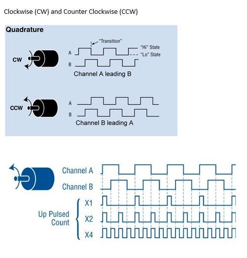
-
USB-1808X using a counter to count pulses from an encoder
PhilipW replied to PhilipW's question in Measurement Computing (MCC)
If I'm using a counter input and specifying MccDaq.CounterMode.Totalize to count the pulses, the data coming from the encoder will be a sequence of increasing numbers? Example: 1 1 1 1 2 2 2 2 3 3 3 3 ... Four data samples create a pulse. The number will eventually rollover to 0 when it reaches the limit for a 32 bit number. -
USB-1808X using a counter to count pulses from an encoder
PhilipW posted a question in Measurement Computing (MCC)
In the example program DaqInScan02, analog input, digital input and a counter input are used simultaneously in a continuous, background mode using DaqBoard.DaqInScan(). I have an requirement to use three analog inputs for reading voltage values and one counter to count the number of pulses per second from an encoder. To configure the counter, can I use DaqBoard.CConfigScan() so I can count the number of pulses per second? I'm passing the following arguements to DaqBoard.CConfigScan(): MccDaq.CounterMode Mode = MccDaq.CounterMode.Totalize; MccDaq.CounterDebounceTime DebounceTime = MccDaq.CounterDebounceTime.DebounceNone; MccDaq.CounterDebounceMode DebounceMode = 0; MccDaq.CounterEdgeDetection EdgeDetection = MccDaq.CounterEdgeDetection.RisingEdge; MccDaq.CounterTickSize TickSize = 0; int MapCounter = 1; Will these values work? The parameter MapCounter participates with the input signal by gating the counter or decrementing the counter. Can you elaborate? -
Replacing DT9801 with USB-1808X
PhilipW replied to PhilipW's question in Measurement Computing (MCC)
Hi Fausto, You indicated that I could use a Timer Output instead of a Digital Output. How? Here is my code for the Digital Output: ushort DataValue = 255; // numeric value to send to digital output MccDaq.ErrorInfo uLStat = daqBoard.DOut(PortOutputNum, DataValue); if (uLStat.Value != MccDaq.ErrorInfo.ErrorCode.NoErrors) { ... } My code is based on your example program ULDO01 which uses DOut(). -
Hello Fausto, Back in January it was announced that the DT9801 was discontinued. I exchanged some emails with you and based on my requirements I selected and purchased a USB-1808X for development. With the DT9801/Open Layers library my application can simultaneously use three analog input channels to read voltages and one digital input to count pulses from an encoder. As well, the application will send a value using the digital output when a condition within the application is met. Using the USB-1808X/Universal library I’ve been able to use three analog input channels and one digital input working simultaneously using DaqInScan(). Digital output uses DOut(). I used your example programs to write my code; ULDO01 uses DOut() and DaqInScan02 uses DaqInScan() to collect data points in continuous, background mode. The technical documentation for the USB-1808X states there 8 analog inputs, 4 digital I/O and 2 counter inputs. When I run your example application DaqInScan02, the following code from the application finds 8 analog channels, 2 counters but only 1 digital port // determine the number of analog channels and their capabilities ChannelType = clsAnalogIO.ANALOGDAQIN; NumAIChans = AIOProps.FindAnalogChansOfType(DaqBoard, ChannelType, out ADResolution, out Range, out LowChan, out DefaultTrig); // determine the number of digital ports, their capabilities, etc ChannelType = clsDigitalIO.PORTINSCAN; NumPorts = DIOProps.FindPortsOfType(DaqBoard, ChannelType, out ProgAbility, out PortNum, out NumBits, out FirstBit); // determine the number of counters, their capabilities, etc ChannelType = clsCounters.CTRSCAN; NumCtrs = CTRProps.FindCountersOfType(DaqBoard, ChannelType, out CounterNum); I was expecting 4 digital ports. Can you explain the digital I/O discrepancy? Regards, Philip
-
Open Layers library and Universal library compatibility
PhilipW replied to PhilipW's question in Measurement Computing (MCC)
For the last two years I've been working on an application that uses the Open Layers library with the DT9801. The application uses three input analog channels to read voltage values and one digital input to read pulses from an encoder. Sampling rate is 10,000 hertz. We plan to sell a couple hundred units over the next five years. The DT9801 has been discontinued and the replacement data logger requires the Universal library. I have a few questions. 1. What year was the Universal Library introduced? 2. Does the Universal Library fix some problems in the Open Layers Library? 3. I have noticed some intermittent/occasional inconsistencies in the sampling of the data using Open Layers/DT9801. Does the Universal Library have better performance for sampling? Regards, Philip -
Open Layers library and Universal library compatibility
PhilipW replied to PhilipW's question in Measurement Computing (MCC)
Hi Fausto, In my application using Open Layers and the DT9801 data logger, I'm reading data using 3 analog inputs (voltage) and 1 digital input. The digital input takes data from a Turck encoder. The data is a square wave and I wrote a function to count the pulses; a pulse contains 4 data samples. These inputs are synchronized/simultaneous. From the DT9800 Series manual: In addition to the analog input channels, the DT9800 Series modules allow you to read eight digital input lines using the analog input channel list. This feature is particularly useful when you want to correlate the timing of analog and digital events. The recommended replacement for the DT9801 is the USB-1608G Series. I reviewed the datasheet and it doesn't appear to support synchronous input for analog and digital sources. Is my analysis correct? The datasheet for the USB-1808 Series indicates the data logger supports synchronous/simultaneous inputs. Would this data logger be a better fit for my application? Regards, Philip -
Open Layers library and Universal library compatibility
PhilipW posted a question in Measurement Computing (MCC)
The DT9801 uses the Open Layers library. The DT9801 has been discontinued and replaced by the USB-1608G Series. The USB-1608G uses the Universal Library. Is the Universal Library backwards compatible with Open Layers so that my software can support the DT9801 and USB-1608G? Do I have to support Open Layers and the Universal Library in my application? Regards, Philip -
We are using the DT9801 and I was wonder if the digital input can support RFID readers? If not, do any DAQs support RFID readers?


